Assembling your kit
You can make your life easy or hard. Your choice!
When assembling your kit, I've found the following is
the easiest, quickest way to procede.
- If you are using the regulator option, cut the link on the component side across pins 1 and 3 of IC2
- Place and solder the SOIC chip. (check orientation. Pin 1 goes nearest the 10-way terminal strip)
- Solder the bypass capacitor adjacent to the IC
- Solder the ground test terminal (gold pin, supplied) if desired
- If you are using the regulator, install the second bypass cap and the 10uF tantalum cap
from the solder side of the board (refer pictures). Note, the tantalum is polarised, the + lead
(the longer lead) goes nearest the edge of the board.

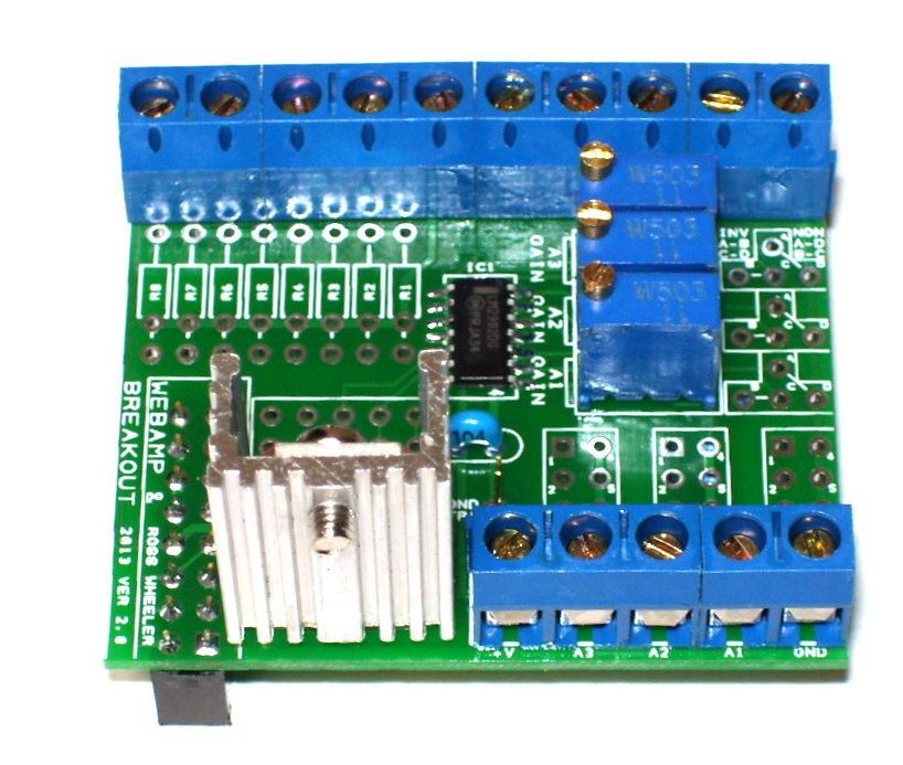
- Put the 16-pin header on the SOLDER SIDE of the board, similarly the 5-pin header.
Place the board on a flat surface, hold it down firmly and solder both connectors.
This should ensure they are flush and square to the board.
- Clip the leads from the 5-pin header as close to the board as possible
- Insert both sets of screw connectors on the COMPONENT side of the board.
Place the board component-side down on a flat surface, hold it down firmly and
solder the screw terminals.
- Insert and solder the 3 20-turn trimpots. The adjustment screw goes nearest the opamp.
(Installing them this way gives an intuitive clockwise turn for higher gain)
- Clip all remaining component tails close to the board.
- Insert and solder the voltage regulator
- Clip the regulator leads, clean the board, let it dry
- Power the board, apply input voltage to the amplifier inputs and adjust gain as required
You can Download the test code
I use here to adjust the amplifier gains and ensure all inputs are working.